The Ultimate Guide to Advanced Smartphone Micro-Soldering and PMIC Power Rail Troubleshooting in 2026
In the modern mobile repair industry, basic hardware replacements like displays and batteries are no longer enough to build a highly lucrative service business. As smartphone circuitry becomes increasingly compact and integrated, hardware technicians must master micro-soldering and PMIC (Power Management Integrated Circuit) power rail diagnostics to solve dead handsets, power drain problems, and thermal throttling issues.
Whether you are an aspiring repair specialist looking to upgrade your technical skills or a certified professional handling complex motherboard repairs, this complete technical guide breaks down the essential diagnostic methodology, equipment requirements, and power rail troubleshooting steps needed in 2026.
What is Micro-Soldering and Why is It Essential Today?
Micro-soldering refers to the microscopic repair, reballing, and trace jumping performed on Integrated Circuits (ICs) and surface-mount devices (SMD) on a smartphone’s multi-layered printed circuit board (PCB).
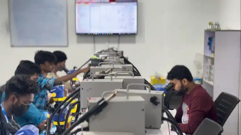
With major smartphone manufacturers utilizing stacked logic boards, sub-millimeter BGA (Ball Grid Array) chips, and highly dense copper traces, standard soldering tools are insufficient. Precision micro-soldering under stereo magnification is required to perform:
BGA reballing for CPU, RAM, and baseband ICs.
Jumper wire installations on broken PCB inner traces.
FPC (Flexible Printed Circuit) connector replacements without melting surrounding components.
Short-circuit clearance on main system voltage rails (VBAT, VPH_PWR, VSYS).
To gain hands-on expertise in using thermal cameras and precision microscopes on live device boards, check out our industry-oriented Professional Diploma in Smartphone Chip-Level Training Course.
Understanding the PMIC Power Architecture
The Power Management IC (PMIC) acts as the heart of a smartphone’s power distribution system. It receives primary battery voltage and steps it down or converts it into multiple regulated DC voltage rails (VREG) required by the CPU, GPU, memory modules, cameras, and display controllers.
Key Power Rails to Monitor During Diagnostics:
VBAT / VBUS Rail: Primary voltage line coming directly from the battery or USB charging port (typically 3.7V – 5.0V).
VPH_PWR / VSYS Rail: Secondary system supply voltage generated by the primary charging IC (e.g., SMB/BQ series ICs).
Buck Converters (VBUCK): High-current, low-voltage lines supplying core voltage (VCORE) to processor execution cores (usually ranging from 0.6V to 1.2V).
LDO Regulators (VLDO): Low-noise linear output voltage lines powering delicate components like sensors, touch ICs, and audio codecs.
Step-by-Step PMIC Power Rail Troubleshooting Methodology
When a smartphone arrives in a “completely dead” state or fails to power on despite a healthy battery, follow this systematically proven diagnostic flowchart:
Step 1: Amperage Draw Analysis via DC Power Supply
Connect the smartphone motherboard to a calibrated 4-digit DC power supply unit (5V / 5A output). Observe the static power consumption prior to pressing the power button:
0mA Static Draw: Open circuit, blown input fuse, or failed charging IC input gate.
High Static Current Draw (>300mA – Auto-consumption): Full short-circuit or secondary leakage on the main VPH_PWR rail.
Fluctuating Low Draw (20mA – 80mA after power key): Boot-loop cycle caused by corrupted eMMC/UFS storage, missing LDO rail voltage, or CPU clock generation failure.
Step 2: Cold Resistance Testing (Diode Mode & Resistance)
Switch your multimeter to Diode Mode (Red probe grounded to PCB shield chassis, Black probe connected to test pads):
Measure VBAT, VPH_PWR, and primary PMIC output capacitors against baseline ground values.
A multimeter reading under 0.010V in diode mode or below 10 Ohms in resistance mode indicates a dead short to ground on that specific rail.
Step 3: Voltage Injection and Thermal Detection
When a shorted capacitor or IC is identified:
Isolate the affected power rail using schematic diagrams and boardview software.
Set your DC power supply to the exact operational voltage of that rail (never exceed the maximum rated rail limit—typically 1.2V to 4.0V depending on the line).
Inject DC current directly into the shorted node.
Utilize an infrared thermal imaging camera or rosin flux atomization to visually pinpoint the component generating localized heat.
Required Professional Tools for Advanced Micro-Soldering
To achieve high success rates in motherboard logic board recovery, your lab bench should be outfitted with industry-standard equipment:
Trinocular Stereo Microscope (7X–45X magnification with 0.5x Barlow lens).
Hot Air Rework Station with precise temperature/airflow calibration (e.g., Quick 861DW or equivalent).
Micro-Soldering Iron Station with fine J-type and C-type soldering tips.
4-Digit Precision DC Power Supply with short-circuit protection detection.
Infrared Thermal Camera for rapid PCB short identification.
UV Mask Light & Solder Mask Compound for trace insulation repair.
Mastering these tools under the supervision of industry professionals is a core part of our hands-on training methodology. You can learn more about our experienced faculty and state-of-the-art facilities on the About Us page.
Common Challenges and Best Practices in PCB Repair
Preventing Thermal Stress: Avoid applying high heat directly over double-decker CPUs or sandwich motherboards for extended periods. Use underfill scrapers safely at 240∘C−280∘C to avoid lifting solder pads.
Cleanliness and Flux Management: Always clean board residue using 99.9% Pure Isopropyl Alcohol (IPA) to prevent stray parasitic capacitance or conductive flux trails.
Using Genuine Components: Always source donor boards or OEM-grade replacement ICs to ensure proper power regulation tolerances.
Conclusion
Mastering smartphone micro-soldering and PMIC power rail diagnostics is the ultimate skill set that elevates a basic hardware repairer into an elite chip-level technician. As mobile technology continues to integrate complex hardware circuits, skilled diagnostic experts will remain in high demand across service centers, independent repair businesses, and consumer electronics hubs.
If you are eager to build a career with hands-on practice, NSDC and STED-recognized certifications, and complete business setup guidance, explore our complete list of technical programs on our Courses Page or discover how our graduates launch successful service centers on our Placements Page.
Frequently Asked Questions (FAQ)
Q1: What is the difference between basic mobile repair and chip-level micro-soldering?
Basic mobile repair involves replacing modular components such as screens, batteries, charging ports, and camera modules. Chip-level micro-soldering involves diagnosing, removing, reballing, and soldering micro ICs, capacitors, resistors, and repairing damaged traces on the smartphone motherboard.
Q2: Do I need prior electronics experience to learn smartphone PMIC power rail diagnostics?
No prior engineering background is required. With step-by-step practical training, schematic diagram reading practice, and real device lab sessions, anyone with basic technical interest can learn motherboard diagnostic procedures.
Q3: What qualifications will I receive after completing chip-level training at NexGen Institute?
Upon completing the course at NexGen Institute, students receive nationally recognized government certifications approved by NSDC (National Skill Development Corporation), STED Council, and Skill India, establishing official technical credentials across India and abroad.
Q4: How long does it take to learn advanced micro-soldering?
Our practical training programs range from 4 months to 8 months depending on the depth of coverage—from fundamental smartphone troubleshooting to advanced iPhone logic board micro-soldering and CPU reballing.
Contact NexGen Institute of Mobile Technology
Ready to start your journey toward becoming a certified chip-level mobile repair expert? Contact our admissions team today for batch timings and course counseling:
Address: Second Floor, NKM Arcade, Ponnurunni, Vyttila, Kochi, Ernakulam, Kerala 682019
Phone / WhatsApp: +91 90618 82000
Email: nexgeninstitutecochin@gmail.com
Website: https://nexgeninstitute.in/
Get in Touch: Visit our Contact Us Page to register for a free demo session.