Mastering Thermal Imaging Diagnostics in Mobile Repair: The Ultimate Guide to PCB Fault Finding (2026)
In the rapidly evolving landscape of advanced mobile phone repair, traditional diagnostic tools like standard multimeters and DC power supplies are no longer sufficient on their own. Modern smartphone logic boards feature hyper-dense multi-layer Printed Circuit Boards (PCBs) packed with thousands of micro-components—including Power Management Integrated Circuits (PMICs), capacitors, resistors, and System-on-Chips (SOCs).
When a dead smartphone or liquid-damaged device suffers an internal short circuit, finding the exact faulty component using conventional voltage-injection or visual inspection can take hours, leading to unnecessary board stress and potential heat damage.
This is where thermal imaging diagnostics has become a complete game-changer for professional hardware technicians. By converting infrared radiation into visual heat signatures, thermal imaging cameras allow repair engineers to instantly locate short circuits, failing ICs, and power rail anomalies in seconds.
In this comprehensive guide, we explore how thermal imaging works in micro-soldering, the step-by-step methodology for isolating logic board shorts, and how specialized hands-on training at a top-tier mobile repairing institute in Kochi can elevate your technical career.
Why Traditional Logic Board Diagnostics Fall Short
For years, chip-level repair technicians relied on the “rosin flux technique” or alcohol evaporation methods combined with a DC power supply to spot shorted components. While these techniques are useful, they have major limitations:
High Risk of Thermal Stress: Excessive current injection to vaporize rosin can delaminate PCB layers or damage adjacent CPU/RAM chips.
Hidden Under-BGA Shorts: Rosin smoke cannot detect shorts underneath Ball Grid Array (BGA) components or under structural EMI shields without complete shield removal.
Time-Consuming Fault Location: Finding a micro-short among hundreds of parallel capacitors on a primary power rail (such as VPH_PWR or VCC_MAIN) can take hours without visual heat mapping.
Thermal imaging solves these operational bottlenecks by providing real-time, non-contact, high-resolution thermal mapping of the entire logic board.
How Thermal Cameras Work in Smartphone PCB Repair
Thermal cameras used in chip-level diagnostics (such as PCB thermal analyzers) operate on long-wave infrared (LWIR) sensors. Every electronic component emitting electrical resistance generates thermal energy.
When a shorted component draws excessive current from a power supply, it emits a sudden surge of heat localized to a few millimeters. The thermal analyzer captures this heat gradient and converts it into a color-coded heatmap on a computer screen:
Cold / Ambient Areas: Represented in blue, green, or dark purple.
Normal Operating Components: Displayed in soft yellow or orange.
Shorted or Failing Components: Highlighted as brilliant white or intense red hot spots.
By pairing high-resolution thermal optics with microscopic magnification, technicians can pinpoint a failing 0402-sized capacitor measuring less than 1mm in size.
Step-by-Step Guide: Isolating Board Shorts Using Thermal Imaging
If you are pursuing advanced micro-soldering, understanding the thermal diagnostic workflow is critical. Here is how master technicians isolate complex motherboard faults:
Step 1: Initial Power Supply Diagnostics & Current Draw Analysis
Before applying thermal imaging, connect the target motherboard to an adjustable DC Power Supply. Observe the initial boot sequence or static current draw:
Instant Primary Short (0V / Max Amperage Draw): Indicates a direct short on VBAT, VCC_MAIN, or VPH_PWR lines.
Secondary Boot Short (Triggers upon pressing power button): Indicates a faulty secondary LDO voltage rail downstream from the PMIC.
Step 2: Board Setup under the Thermal Analyzer
Remove all thermal pads, camera modules, and flex cables from the logic board. Mount the board securely on a ESD-safe diagnostic platform beneath the infrared thermal camera lens.
Step 3: Low-Voltage Current Injection
Set your DC power supply voltage below the target rail limit (typically 1.0V to 3.8V depending on the power line) with a current limit of 1A to 2A. Inject voltage directly into the shorted rail using fine-tip probe leads.
Step 4: Real-Time Heatmap Analysis
Observe the PC monitor running the thermal mapping software. Within milliseconds, the exact shorted component will glow white-hot.
Pro Tip: If the main PMIC lights up immediately, do not immediately assume the PMIC is faulty. A shorted decoupling capacitor on a secondary output line connected to that PMIC will often reflect heat back into the chip. Advanced training in schematic analysis is crucial to differentiate between heat generation and heat absorption.
Step 5: Micro-Soldering Component Replacement
Once identified under the thermal camera, verify the component under a stereo microscope. Use hot air rework equipment and high-purity flux to remove the shorted SMD component and replace it with an OEM-grade replacement.
Key Advantages of Master Class Thermal Diagnostics
Specializing in thermal imaging and micro-soldering provides distinct competitive advantages for smartphone repair technicians:
Feature Traditional Diagnostics Thermal Camera Diagnostics Fault Location Speed
30 minutes to 2 hours
5 to 15 seconds
Component Safety
High risk of thermal over-stress
Minimal risk due to low voltage injection
Diagnostic Accuracy
60% – 70%
95%+ precision
Under-Shield Detection
Requires removing all EMI shields
Detects thermal leakage through shields
Professional Efficiency
Low repair throughput
High repair turnaround & profitability
Whether you are aiming to open your own high-end service center or secure lucrative technical jobs in India or abroad, mastering thermal imaging techniques is essential to remaining competitive in modern mobile repair.
Why Hands-On Training Matters: Choosing the Right Institute
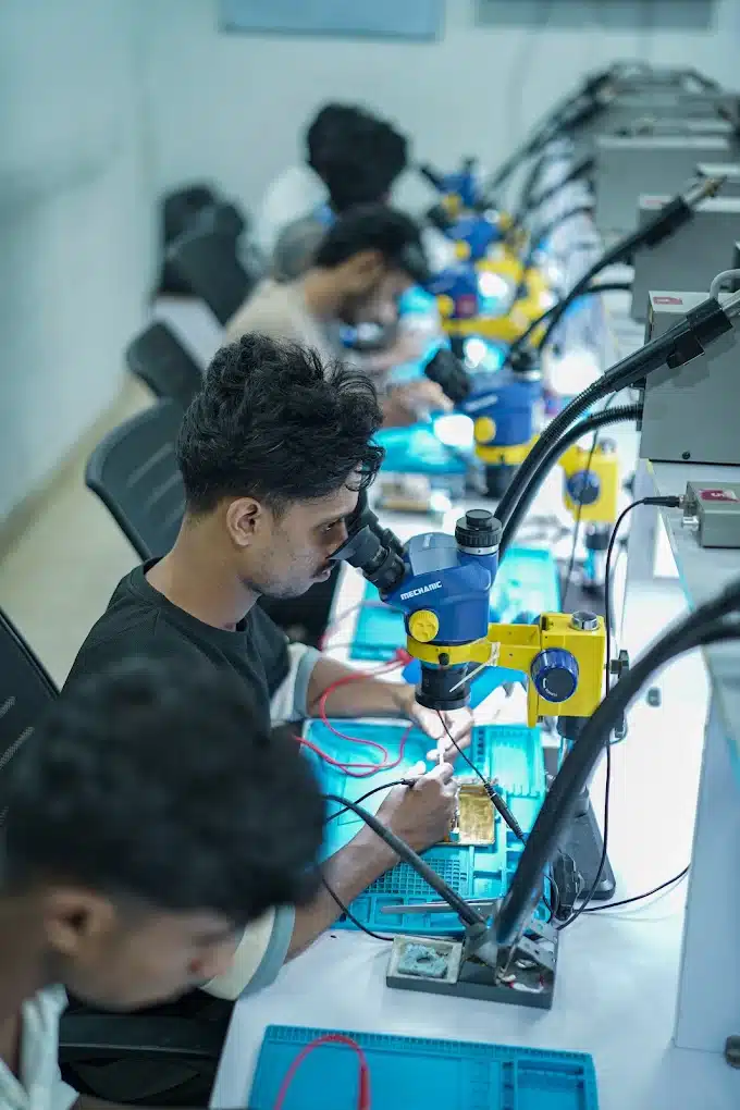
While understanding the theory behind thermal diagnostics is straightforward, mastering the technique requires hands-on experience under expert supervision. Working with microscopic components, complex schematics (such as ZXW or Borneo Schematics), and precision infrared camera calibration requires practical exposure in a dedicated lab environment.
At NexGen Institute, students gain real-world diagnostic experience using state-of-the-art tools and real device motherboards. You can explore more technical diagnostic tips, PMIC power rail troubleshooting, and micro-soldering guides by visiting the official NexGen Institute Repair Blog.
Through practical lab sessions, certified instructors guide you from basic multimeter measurements to advanced logic board restoration, helping you build a successful technical career.
Frequently Asked Questions (FAQ)
Q1: Can a thermal camera locate all types of logic board faults?
While thermal cameras are exceptionally fast at locating short circuits and high-current leaks, they cannot diagnose open circuits (broken traces) or logic bugs. Open circuit troubleshooting requires voltage testing using a digital multimeter and schematic diagrams.
Q2: Do I need advanced micro-soldering skills to use thermal diagnostic tools?
Yes. Locating a faulty component with a thermal camera is only half the job. Removing micro-components, reballing ICs, and replacing BGA chips require advanced hands-on micro-soldering skills.
Q3: What qualifications do I need to join a chip-level mobile repairing course?
No prior engineering degree is required. Anyone who has completed high school (+2) or secondary education with a passion for electronics and hardware technology can enroll in chip-level training programs.
Q4: Are thermal imaging diagnostic techniques covered in NexGen Institute courses?
Yes! NexGen Institute provides comprehensive hands-on instruction covering thermal camera diagnostics, schematic reading, power rail troubleshooting, and chip-level micro-soldering.
Ready to Upgrade Your Mobile Repairing Skills?
Step into the future of advanced smartphone diagnostics with industry-recognized certification and 100% practical training.
Contact NexGen Institute Today:
Address: Second Floor, NKM Arcade, Ponnurunni, Vyttila, Kochi, Ernakulam, Kerala 682019
Call / WhatsApp: +91 90618 82000 | +91 90618 72000
Email: nexgeninstitutecochin@gmail.com | info@nexgeninstitute.in
Official Website: nexgeninstitute.in
Working Hours: Monday – Saturday | 9:30 AM – 6:00 PM